The Cutts compensator was originally developed as a device that reduced recoil (35-46% depending on the load used) in large bore long guns. It later morphed into a device that also allowed for changeable chokes. As it was available before screw in chokes were commonly available this was a
The Cutts compensator was invented by Colonel Richard Malcolm Cutts, USMC.
gunsmithing notes:
- The published instructions for attaching a Cutts Compensator state:
Instructions
for attaching
CUTTS
COMPENSATOR
Cutts Diamond Logo Image
COMP
Trade Mark Reg US Patent Office
The Lyman Gun Sight Corporation
Middlefield, Connecticut
DIRECTIONS FOR ATTACHING
STYLE A COMPS
Used on 12 – 16 – 20 & 28 Gauge Guns
OPERATION 1. Cut off
barrel with hacksaw 22 1/8″ full, measuring from the base of a shell in the chamber.
OPERATION 2. Face end of barrel smooth and reasonably true with the bore. A counter-bore with a pilot
approximatel y .725″ is best for this purpose. Remove burr from the bore at this point with a scraper.
OPERATION 3. Set the barrel on centers in a lathe using an arbor which fits the chamber and extends about 2″ beyond the end of the barrel extension to permit the attachment of a lathe dog. The barrel can be set with the tail center in the muzzle and will be on the
chamfer edge mentioned in the previous operation. NOTE: It is well to remember at this point that different makes of shotguns are a different diameter on the outside and often times barrels of the same make will vary considerably. The average Remington Automatic barrel will measure approximately .835″ before it is turned although some will run much smaller than this and some Winchester Model 12’s will run as low as .800″. For thisreason the adapter which is to be brazed to the barrel is made with different diameters on the inside. With the barrel on centers in the lathe turn the muzzle back about 29/32″ with, if possible, a slight taper towards the muzzle. The adapter selected, and it is advisable to the largest size that each individual barrel will take, should be fitted so that it can just be forced on by hand down to the end of the turned portion to avoid any chance of its tipping. This adapter is then ready for brazing or preferably silver soldering which will be mentioned later. CAUTION: Winchester Model 12 barrels with solid rib must be handled with care. These ribs are soft soldered to the barrel and will easily loosen. When turning the muzzle to fit the adapter cut most of the rib away with a hacksaw and face end of rib with care. When silver soldering adapter in position keep barrel just behind adapter cool, preferably with small stream of water to prevent loosening rib.
It is extremely important that certain precautions be taken both in the selection of’ an adapter of the proper size and also In the preparation of the barrel to fit the adaptor. When the barrel is of such size that a .825″ or an .840″ adaptor (12 gauge) is possible, it is quite alright to turn the barrel down to fit the adaptor. If, however, the barrel is too small to use one of these and will require one of the smaller ones such as the .812″ or in extreme cases the .795″, the best procedure is to true the barrel up to maximum diameter and then bore out the adapter to fit. This will leave as much strength as possible in the barrel and result in a stronger installation. Some barrels are so small it is hardly possible to clean them up to take the .795 adapter and when this occurs it is best to true them up so that they clean about two-thirds of the way around and then bore the adapter to fit snugly.
The portion of the barrel that has not been turned away should be polished bright with emery cloth so that the silver solder will flow and fill in this slight hollow, which will result in a joint that is quite satisfactory. All of the information above has referred to 12 gauge sizes only, but the same applies when the smaller diameters are used in the other gauges, such as the .740″ adapter for 16 gauge and the .690″ adapter for 20 gauge. The 28 gauge barrels being the same outside diameters as the 20 gauge but with smaller bore do not give any trouble.
VENTILATED RIBBED BARRELS
When attaching to ventilated ribbed barrels it is advisable in all instances to mount the adapter immediately ahead of one of the supporting posts. This means the barrel must be cut off a little over 7/8″ ahead of the appropriate post and turned down to fit the adapter and, at the same time face off the end of the rib. Extreme care must be taken to avoid loosening the rib when this operation is done and it is usually best to attach a small clamp on the rib at this point as a safety precaution. Where the rib is low enough to harmonize well with the level on the back of the Comp adapter the adapter may be used as issued. Where the rib is high it is usually advisable for the sake of appearance to face off the back of the adapter slightly in order to reduce the amount of bevel and bring it approximately flush with the top of the rib. Sometimes all of the
bevel must be removed. As mentioned above in connection with the Winchester Model 12 solid rib barrels which are soft soldered on, extreme care must be exercised when soldering the adapter to some of these ventilated ribbed jobs where the posts may be attached to the barrel in the same way as theWinchester rib, so this must be kept cool to prevent the solder from loosening. CAUTION: If the installation is not made immediately forward of one of the supporting posts as mentioned above, it means there will be an unsupported portion of the rib overhanging which is easily damaged, and experience has shown this to be unsatisfactory. It does preventyour obtaining an exact barrel length in most instances, but as practically all guns are cut so that when Comp and Spreader tubeare in place you will have a 26″ barrel, most of the posts come so that not much deviation is necessary. The Model 31 Remington will come about 27″ and the Model 12 Winchester comes to about the same length.
OPERATION 4. Remove the adapter and coat the inside with Flux and reassemble by hand. Be sure to coat this thoroughly as the silver solder will not adhere and you will not get a satisfactory joint unless all surfaces are covered, Rotate the adapter on the barrel to be sure that the Flux has made good contact with the turned surface of the barrel. Do not coat the last 1/8″ toward the rear of the adaptor as this will discourage the possibility of the solder’s running clear through if the adapter is not quite so tight as it should be. Stand the barrel in a vertical position and apply torch flame to
threaded portion of adaptor keeping the flame well toward the end. As soon as the work begins to show signs of red, the Flux will melt and the silver solder can be fed into the trough or groove between the barrel which protrudes beyond the adapter and the bevel that is cut in the adapter proper. Continue to heat and feed the solder to it until it flows down through the joint and begins to appear at the telltale hole drilled at the base of the thread for this purpose. Do not use any more heat than is necessary for the solder. to flow. Allow the barrel to cool.
The silver solder that is recommended for the preceding operation is the only type of solder that is satisfactory for this work. Soft solder will not give so good a joint and results over a period of years have shown that much trouble will be encountered. The particular brand of silver solder we recommend is not essential, but we encourage its use because it is readily obtainable through any source of welding supplies throughout the country and it has a
relotively low melting point which makes it easy to use. It also gives an excellent joint. Se sure to use the Flux that can be purchased with it for thia purpose.
OPERATION 5.
Face of the extra 1/32″ of the barrel beyond the end of the adapter and excess solder using the same counter-bore with which the barrel was faced originally. This is most easily accomplished with the arbor in the chamber of the barrel on the tail center of the lathe and the counter-bore held in a lathe chuck. The barrel can be held from rotating by hand and fed against the counter-bore with thetail stock gradually. Mount the barrel on centers again and true up the shoulder of the adapter and cut away any solder that may have run through the telltale holes and into the recess.
OPERATION 6. Polish the outer diameter, bevel and
rear face ofadapter with emery cloth on a stick and blacken with whatever means available. One of the various aqueous solutions for blacking steel which boils at about 300 degrees is best as the tip of the barrel can be dipped over the adapter. Further mention of this blacking process will be made later. The barrel is now ready to attach the Compensator and the thread on the adapter itself need not be touched further except to brush off any dirt which may have accumulated in the threads. Screw the Compensator on to the adapter until it is against the shoulder. When turned up by hand the rear sight should lack about 1/16″ of lining up in the vertical position and as this will not occur on the first trial, except by chance, the barrel is then mounted on centers and sufficient faced off the shoulder of the adapter to bring the front sight in the position mentioned. When this has been accomplished the barrel is held securely in a padded vise and a strip of steel which will pass through the rear ports of the Compensator, preferably with a wooden handle attached, is used to force this against the shoulder sufficiently to bring the sight in its proper upright position. NOTE: If a micrometer carriage stop is available on the lathe and it is remembered that one turn on a 28 pitch thread is approximately .036″ or a quarterturn . 009″, the proper amount can be removed with one or two trials.
OPERATION 7: With the Compensator securely on the adapter with the sight in its proper position and with approximately 1/16″ of draw on the thread; that is, forced 1/16” beyond the point where it first touches the shoulder, it is now ready to insert the anchor screw With No. 20 or No. 21 drill spot through the anchor screw hole in the Compensator into the adapter a short distance sufficiently so that when the screw is inserted and set up as tightly as possible it will be approximately flush with the outer surface. The Compensator is now fully fitted.
The preceding operation is very important as it is absolutely essential that the Compensator body be forced into position for the last short distance to relieve the strain on the threads and to prevent its loosening under vibration. The anchor screw is just an added precaution and will have no real work to do.
VERY IMPORTANT
On Auto-Loading shotguns the Compensator as installed above is ready for use, but on slide action repeaters such as the Winchester Mod 12 and the Remington Model 31 a slight bending or adjusting for the Compensator is necessary to prevent the gun from shooting below center when sighted in the normal way. Take a piece of 3/4″ steel bar and thread a short head on one end about 1 1/4″ in diameter. This can then be turned down for a distance of ½” to 1.100″ and threaded with 28 threads per inch to the shoulder, to duplicate the thread that is on the pattern tubes. This thread dimension is for 12 gauge only. The 16 gauge thread is .982″ x 28 and the 20 gauge is .920 x 28. Holding the body of the Comp between “V” blocks lined with paper just over the point where it is threaded to the barrel and with the block just clearing the rearward port, screw the rod mentioned above into the front end of the Compensator. It is desirable to have the front sight, in this instance, horizontal and then pressure can be applied towards the sight to bend the compensator slightly upward. On most of the slide action guns a movement of from .025″ to .030″ is sufficient and some guns will require less. This bending is not noticeable but can be checked with a straight edge along the bottom of the Compensator. After having done this- once or twice it will be a simple matter to adjust these to bring the point of impact where it should be and in most instances the gun should shoot the center of the pattern at the center of the hold when sighted closely across the top of the receiver and the top of the front sight. It is recommended that this firing be done at 25 yards with a small sighting spot not larger than one inch which will permit very close holding.
This operation of adjusting the Compensator after being applied to slide action repeaters is very important and it is a point that is frequently ignored or forgotten by outside gunsmiths making this installation. If this adjustment is not performed and the gun is tested it will result in a job that will shoot noticeably below the point of aim and the and the customer will not find it satisfactory. It is well to point out al this time that an occasional individual will prefer that the Compensator be left true with the bore without adjustment as he habitually shoots with his head above the receiver and “sees more barrel” as the saying goes which results in the pattern being thrown high and eliminates the necessity for this adjustment.
BORE DIMENSIONS OF ADAPTERS AVAILABLE
12 gauge – .795, .812, .825, .840, Blank.
16 gauge – .740, .765.
20 and 28 gauges – .690, .715, Blank.
NOTE-Blanks are smaller than any barrel and must be bored to size. The 20 ga. blank is suitable for use on new Rem. 28 ga.
SPECIAL APPLICATIONS
Remington Model 11, 28 gauge
The advent of the Rem.
-48-28 ga. has complicated the situation somewhat as some of these guns do not eject well when the steel Compensator is used and when this occurs, the aluminum model is a must. All of the guns that we are fitting for Remington factory installation Mll have the black aluminum body on them and if your gunsmiths run into any trouble this information may be of some assistance to you.
The barrel on this new gun is also much smaller than the Winchester Model 12, 28 gauge that has been on the market for some years, and so we are now supplying all 28 gauge Comps with blank adapter measuring about .625″ in the bore. This has to be bored out to fit the various barrels as they occur and in this way avoid reducing the barrel diameter any more than absolutely necessary. This seems to be the best thing to do at the moment, at least until there is enough of these on the market so that we can establish a size that will be satisfactory for them. We are calling this to your attention
for the information of your customers and gunsmiths.
When attaching the Comp to a Rem. M11-48 (all gauges) it is not advisable to make the barrel length any shorter than 26″ with Comp and Spreader tube. Any length much shorter will cause interference between the forearm and Comp body when the gun is taken apart, with a risk of damage to the forearm.
REMINGTON MODEL 58
The new Remington Model 58 gas operated autoloader presents a slightly different problem as far as the installation o{ Cutts Compensators is concerned. The functioning of the gun is actuated by the gases of the discharging cartridge which pass through an orifice in the barrel and pressure is transmitted to the mechanism in that way. This orifice, which is on the
under side of the barrel inside the magazine ring, is .128″ in diameter.
We have fitted a reasonable number of these guns with Compensators and there has been no trace of failure to function, that
is eject the fired case and reload. It is possible that on some guns and with certain loads, this trouble could occur and we are advised by the Remington Arms Company that this orifice can be enlarged to as much as .140″ (#28 drill) if necessary. This can be readily done by pushing a pin of suitable size, or possibly a #30 drill, into this orifice and clamp it in a vise until vertical and then it can be enlarged easily in a drill press. It might be well to do this one drill size at a time, enlarging the hole from .128″ to .136″ with a #29 drill and trying it and not enlarge it to the #28 drill size unless necessary. As far as we have been able to learn, this is the only way of controlling the action on this particular model.
HIGH STANDARD MODEL 60
The High Standard Model 60 autoloading shotgun, which is also gas operated, requires special attention. To begin with, all of the models that we have handled are solid frame guns without a take-down and the barrels are very securely set up into the receiver. Due to the nature of this receiver, and the fact that it could be easily damaged, we do not believe that any attempt should be made to remove this barrel so the Compensator can be attached in the normal way. We have, here at our plant, made a special fixture, at considerable expense, to fit the spindle nose of the lathe to hold this gun by the receiver in such a position that the’ barrel will run true and the outer end can be supported on the tail center as in a normal fitting. This permits the adapter to be fitted in the usual manner and the attachment completed. A fixture of this kind is much too expensive for the average installer to
make up and we suggest that any of our installers, with guns of this model to attach, should send them into us and let us handle them here. This will avoid turning away customers and we are able to give one week or less delivery under normal conditions.
The functioning of this gun is very similar to that of the Remington Model 58 and the gas port is in the same location. The standard port is .080″ (#46 drill) in size and can be enlarged to .096″ (#41 drill) if necessary. In other respects, the handling of this is the same as mentioned above in connection with the Remington Model 58.
Win. Model 59 “Win-Lite” (Fiberglass) Barrel
The attachment of the Cutts Comp to this Glass Barrel is similar in most respects to the procedure in common use on conventional steel barrels. The steel liner is very thin and must not be reduced when the glass coating is removed. The fitting of the adapter is accomplished by the use of special low temperature (650°-700° F)
non lead solder and Epoxy adhesive. Normal silver solder such as used for fittings to steel barrels must not he used as the higher heat necessary (1100°-1150° F) will injure the glass coating as well as the steel liner.Naturally an entirely different adapter than that used for steel barrels is required. These adaptersas well as the solder and Epoxy adhesive recommended will be mentioned later.
OPERATION 1. After deciding on the final length of
barrel and choke, cut offbarrel with hacksaw allowing 1/16″ for finishing end. If cut off at 22 1/8″ measured fromhead of shell inchamber , the finished length with Comp and Spreader tube will be 26″. Other lengths desired can be figured from this point.
OPR. 2.
Face off end ofbarrel as in OPR. 2 for steel barrels. (see regular in instructions.)
OPR. 3. Set barrel on centers in
lathe the same as with steel barrels. Turn off the glass coating for 11/16″ from muzzle taking care not to cut into the tube. Then tµrn a 10° taper on the glass coating toward the rear as indicated in the sketch below.
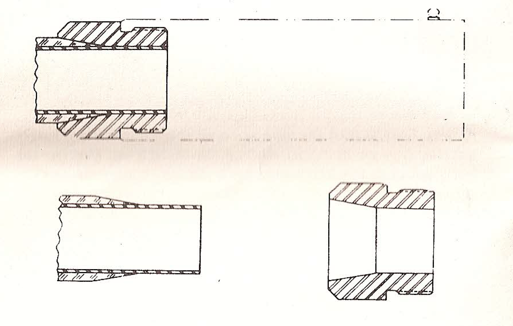
The straight turning and the taper can be accomplished at one operation by setting the lathe compound at 10°. The straight part can then be turned with the carriage and the taper with the compound. Polish the exposed portion of the tube with fine abrasive cloth.
OPR 4.
Select or bore out an adaptor that is .004″ larger than the steel tube liner. Polish this bright on the straight portion. Using Eutectic #157 Solder and #157 Flux,tin the straight portion of the adapter and polished portion of the barrel liner and wipe off excess solder. Use small gas torch such as those propane torches in common use. Do not overheat, 650° F approximately is enough.( Sec Eutectic Instructions) To overheat may spoil liner or coating.
OPR. 5.
Clean tapered surface ofadapter and tapered plastic of barrel with Acetone. Apply the Epoxy adhesive to both tapered surfaces. Do not apply on tinned surfaces. Place adapter in place on barrel end and after rotating slightly to get surfaces together, press firmly onto taper to eliminate excess adhesive. About .005″ thickness of bond is correct. Wipe off excess adhesive leaving a small fillet at rear ofadapter . Stand invertical position with adapter uppermost to cure at room temperature for twenty-four hours.
NOTE: It is possible to simplify the fitting of Comp Body to
adapter by trying the Comp and Adapter assembled in place and mark adapter and barrel so that Front Sight will be just short of in line with barrel center. This will permit a small amount of pressure to bring the Body securely against the shoulder.
OPR. 6. After curing the adhesive twenty-four hours, hold the barrel upright and apply the torch to
extreme end, heating it just enough to melt the solder and permit you to feed enough more to fill the Joint. Cool before removing from vertical position.
OPR. 7. At this point reface the end of
barrel to remove the 1/16″ oftube that has extended beyondend ofadapter . This was left long to make it easier to add solder to the joint. Now proceed starting with OPR. 5 of regular instructions.
Special items required:
Adapters for 12 gauge glass barrels.
Available from us with Comp Body or separately.
Eutec. #157 Solder
Eutec. #157 Flux
Address:
EUTECTIC WELDING ALLOYS CORP.
40-40 172nd Street
Flushing 58, New York, N.Y.
Epoxy Adhesive
Resiweld Plastic Alloy #600
Address:
H. B. FULLER CO.
255 Eagle St
St. Paul 2, Mlnnesota
MATERIALS AND SMALL TOOLS REQUIRED
Hacksaw, w, preferably 32 pitch blades.
Scraper made from
three cornered file.
Silver Solder 1/16″ Wire, We recommend Easy-Flo supplied by Handy and Harman, 82 Fulton Street, New York City 7, New York. With this is used Handy Flux supplied by the same concern. This is available through any source of welding supplies throughout the country.
Blacking Bath. We recommend Du-Lite B as made by the Du-Lite Chemical Corp., Middletown, Conn., who will supply full instructions. This could be handled readily in a heavy metal container with some means of heating in quantities of one or two
gallonss which would do nicely for this work.
DIRECTIONS FOR ATTACHING 410 GA. CUTTS COMPS.
Before preceding with the actual instructions for mounting 410 ga. Cutts Compensators, we wish to refer to the two types available and the guns to which each is adapted.
First, there is the standard steel model which has been on the market for many years. This has 10 straight ports, is made of steel, blackened and is supplied with steel tubes. This steel model is the one to use in Winchester Model 42 and any other 410 gauge gun with single barrel except Auto-loaders such as the Remington Model 11-48, 410
ga .
Second, there is the aluminum model designed for the Remington Model 11-48, 410
ga . and any other auto-loader. This has four ports angled forward and is supplied with aluminum tubes. This model is furnished in black or natural finish aluminum. Black supplied unless otherwise specified. This model is required on the Remington 11-48 as no other will function properly.
In addition to the two models mentioned, there is still a quantity of the original aluminum Compensators in
black and natural finish in the hands of dealers and gunsmiths. These have the ten straight ports and are identical to the steel model and suitable for the same guns but not for the auto-loaders.
All of the above 410 ga. Compensator bodies are supplied with
thread at the rear end of .562-40. This will fit almost all barrels regardless of make or model. For the occasional smaller barrel, they can be obtained with .550-40 thread. These are stamped onrear end withletter “S”.
OPERATIONS OF MOUNTING
OPR. 1. Cut off
barrel to 21 9/16″ measured from head of shell in chamber. This will give over-all length with Comp and Spreader tube of 26″, 26 1/4″ with Modified tube, and 27 1/4″ with Full Choke tube. On ventilated rib barrels, cut about 5/8″ ahead of supporting post to give as near as possible desired length.
OPR. 2. Face end of barrel smooth. A 5/8″ diameter
c’bore with .400 pilot is very convenient.
OPR. 3. Set up on centers in
lathe , using chamber arbors similar to those used on other gauges. Turnend ofbarrel for a distance of 5/8″ to .559″ approx.Cut thread with a single point tool to a length of at least 9/16″. Check lit with Compensator body from time to time as fit must be just as tight as can be turned on. When fitting or trying aluminum bodies we always have oil on the thread. When suitable fit onthread is obtained, turn the body on far enough to cover turned portion and adjustposition of front sight so it will line up exactly with barrel or rib.
A wrench made of flat stock, similar to that used for the larger gauges, can be used to turn up the body on the thread when the models with straight ports are involved. The aluminum model with angular ports requires a short length of 1/4″ drill rod which will clear the drilled holes just to the rear of and in line with the ports.
OPR. 4. With
body in exact alignment, drill through screw holes in both sides with #31 drill and into the bore. Tap with #6-48 tap and insert anchor screws, setting them up as tightly as possible. Using a small half round file, file ends of screws, which project intobore , flush withinside ofbarrel . Polish bore at this point with fine emery cloth, wrapped onwood rod held n lathe chuck.
OPR. 5. Refer to paragraph marked “Very Important” following OPR. 7 on Style A Comps used on larger gauges: Shoot gun to check point of impact and then adjust if necessary and re-test. Test all guns whether slide-actions or auto-loaders.
IMPORTANT
Do not attempt to use any other than aluminum with angular ports on Rem. M11-48, 4l0 p;11. as this mechanism is so delicately balanced that malfunctions will occur with
standard model, even in aluminum.
A very handy tool for use in setting up the Comp body on the thread is readily made from a small piece of hardwood 3/4″x1 1/2″x12″ long. Drill a 1′ hole in the center of the flat side. Cut a groove a little over 1/4″ wide and 5/16″ deep lengthwise on the flat side. This will pass through the center of the 1″ hole on one face. This can be slipped over the Comp body with groove toward the rear and the l/4″ rod used to turn body will slip into
groove . This will give more leverage, be easier on the hands and preventfrom bending. Use in OPR. 3. rod
THE LYMAN GUN SIGHT CORPORATION
MIDDLEFIELD, CONNECTICUT
FORM CCl-5M8-67
PRINTED IN U. 5. A.
- …
document(s):
- Cutts Compensator installation instructions.pdf
- Cutts Compensator.pdf (on Lyman Products website)